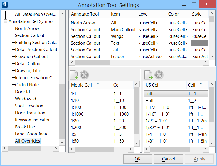
| Lists the override annotation graphics settings for
the selected tool.
Each annotation graphic is composed of one or more
cells, which are stored in a cell library. For example, the Drawing Title
graphic is composed of two cells, one for the main callout and one for the
leader. Each annotation tool has tool settings that correspond to each cell
used in the annotation graphic.
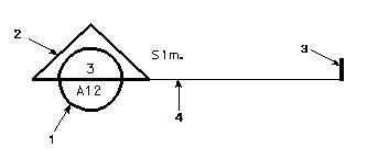
Annotation
graphic parts:
(1) main callout;
(2) wings;
(3) tail;
(4) leader.
To override the settings for an annotation graphic,
select the annotate tool (left side) and then select the attribute (right side)
in the applicable column and row to open an override settings dialog. Complete
override settings and dismiss the override settings dialog.
The following attribute settings can be modified for
the various cells that make up annotation graphics:
- Annotate Tool — The
annotation tool for which settings are completed.
- Item — The cell
that defines the graphic element.
- Level — The level
upon which the graphic element is placed.
- Color — The color
of the graphic element.
- Style — The line
style of the graphic element.
- Weight — The line
weight of the graphic element.
- Cell — The cell
name and cell library of the graphic element.
- Font — The font
used with the graphic element.
- Type
- For leader
lines – the type of line element; line-string or B-spline.
- For terminators
– the type of terminator that is placed on the leader line.
- Length — The length
of the drawing title.
- Radius — The radius
of the graphic element symbol.
|
 Used to modify the
appearance of datagroup annotation cells or Building annotation tool graphics.
The Annotation Tool Settings are used to modify the symbology (color, style,
weight) and change the level of an annotation symbol graphic, or to substitute
a different cell for an annotation graphic.
Used to modify the
appearance of datagroup annotation cells or Building annotation tool graphics.
The Annotation Tool Settings are used to modify the symbology (color, style,
weight) and change the level of an annotation symbol graphic, or to substitute
a different cell for an annotation graphic.
 Annotation
Tool Settings
Annotation
Tool Settings